A device for protecting UAVs from interceptor drones in the 3.3 and 5.8 GHz bands. DUO continuously scans the spectrum, finds an active analog FPV video channel, and automatically activates the corresponding jammer transmitter — without operator intervention.
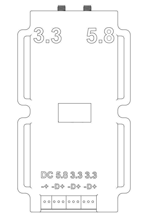
160 × 90 mm
▲ antennas 3.3 · 5.8 GHz
▼ terminals: DC, VTX
01Complete system package
| DUO detection and control unit | 150 g |
| Receiver-path antennas for 3.3 GHz and 5.8 GHz | ~30 g |
| Video transmitter AKK Alpha 10W (4.9–5.8 GHz, 80 channels) + antenna 5.8 GHz | ~70 g |
| Video transmitter Kimpok 3.3 GHz 10W (variant A — 16 channels, 3170–3470 MHz; variant B — 80 channels, 3060–3840 MHz) + antenna 3.3 GHz | ~70 g |
Total weight: ~320 g
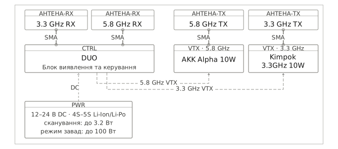
DUO system diagram
02Objective monitoring tools
Separate monitoring tools are required to objectively verify that jamming is actually affecting the adversary's real video channel.
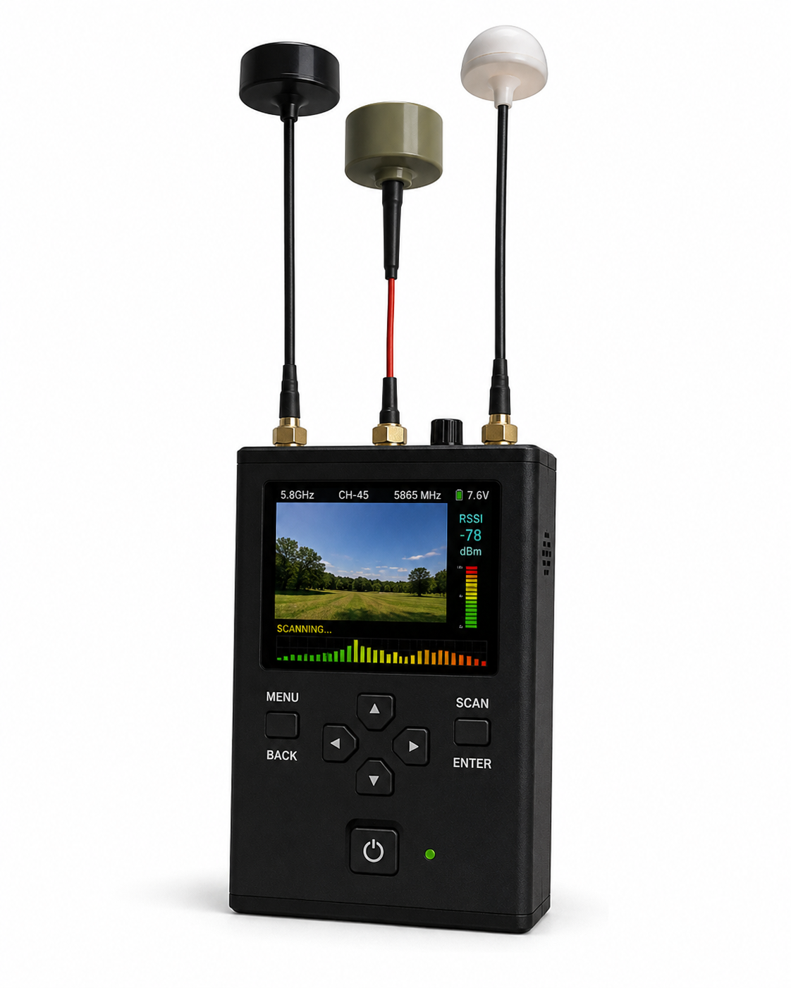
FPV video scanner
A portable FPV video scanner allows the operator to independently monitor the radio spectrum — the RSSI level (received signal strength indicator: the higher the number, the stronger the signal), active channels, and real-time changes in signal strength — in parallel with DUO operation. When jamming is effective, the scanner detects reduced stability of the adversary's video signal, the appearance of noise, or a sharp drop in reception level — confirming that the interference is actually covering the channel.
If the scanner model can also capture and display the channel image itself (not only RSSI), this provides an even more direct check: the operator sees whether the adversary's image actually breaks up or disappears when DUO jamming is activated — rather than seeing only indirect indicators such as signal level.
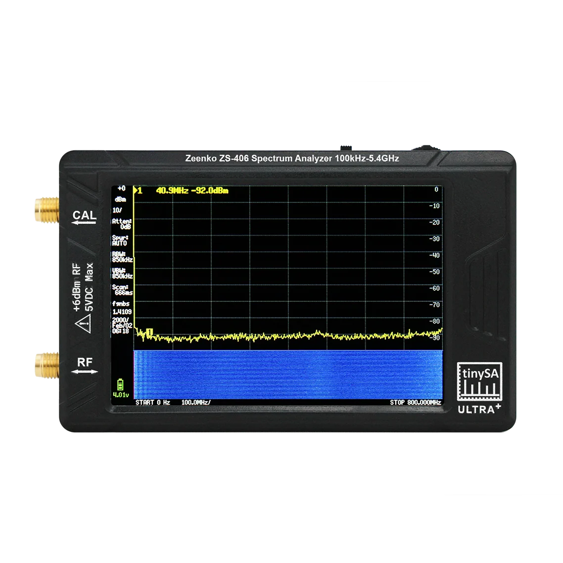
TinySA — portable spectrum analyzer
The portable TinySA spectrum analyzer lets you view the actual radio spectrum directly and additionally verify:
- that the frequency to which DUO tuned the jammer VTX actually corresponds to the detected channel;
- detection of spurious (harmonic) components — the transmitter may also emit on frequencies other than the primary one, which can cause DUO to detect this spurious frequency rather than the set one (see “Troubleshooting”);
- confirmation of the actual level of adversary-signal suppression over the air, rather than relying only on the device indication.
03Power specifications
| Input voltage | 12–24 V DC |
| Recommended power source | Li-Ion / Li-Po 4S–5S |
| Consumption, scanning mode | up to 3.2 W (0.13 A @ 24 V; 0.18 A @ 16 V) |
| Maximum consumption | up to 100 W (when jamming signals in both bands) |
If operation from an onboard supply above 24 V is required, high-quality DC-DC converters must be used.

04Operating principle
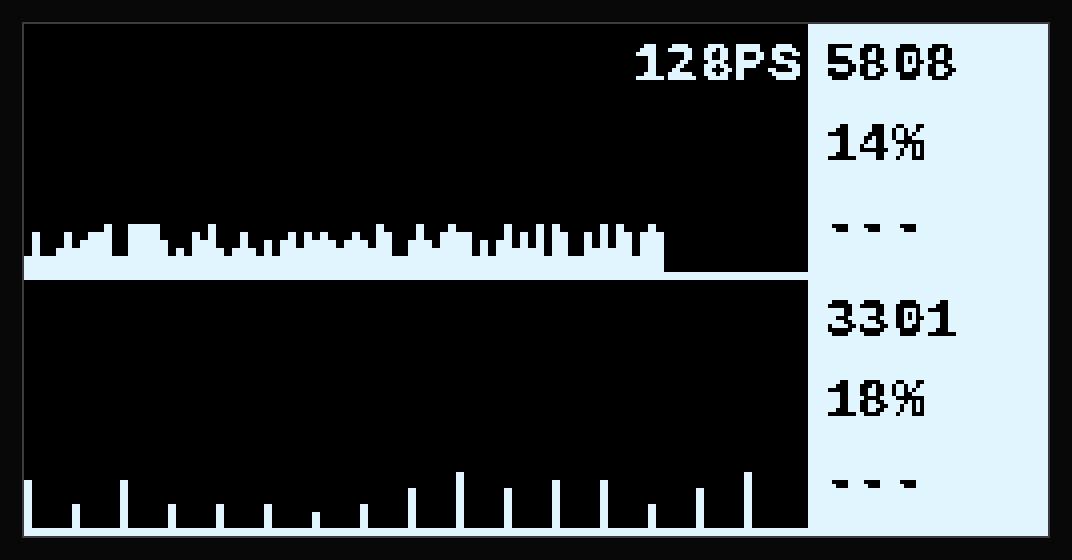
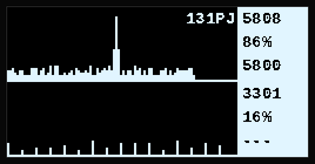
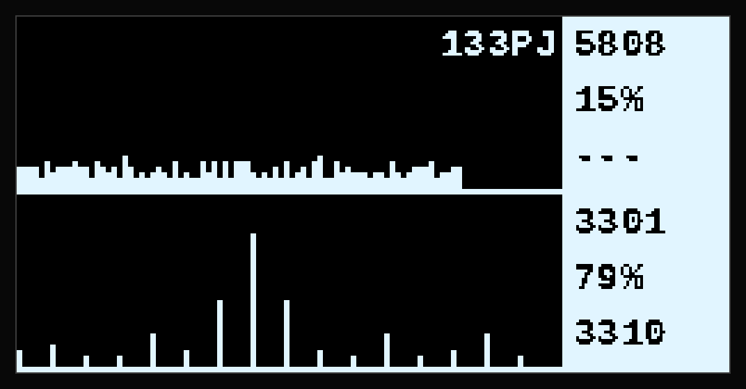
DUO continuously scans both bands in cycles — 80 channels at 5.8 GHz (4990–5945 MHz), followed by the 3.3 GHz channels in the active table (variant A — 16 channels, 3170–3470 MHz; B — 80 channels, 3060–3840 MHz; C — 101 channels, 3000–4000 MHz; see section 05). If the signal level on a channel exceeds the detection threshold, DUO tunes the corresponding jammer transmitter to the same frequency and activates jamming for the set time, after which scanning continues.
The 128×64 OLED screen displays this process live — separately for each band: a histogram of signal levels across all channels on the left, and a panel showing the current strongest channel and its RSSI on the right. The upper half of the screen is 5.8 GHz; the lower half is 3.3 GHz.
Scanning performance
The full cycle depends on the table variant 3.3 GHz: ~3.2 s (A) · ~5.5 s (B) · ~6.3 s (C). The 5.8 GHz pass is unchanged; values marked * are calculated (≈36 ms per receiver-path channel 3.3 GHz), to be verified against the firmware.
The response intervals shown are calculated for variant A (16 channels at 3.3 GHz). For variants B and C, the full cycle is longer (see the card above), so all these intervals increase proportionally.
Simultaneous operation in two bands
DUO detects and responds to signals in both bands in parallel within a single scan cycle. Frequency changes, signal loss and appearance, and simultaneous activity in both bands are handled correctly and independently.
Detection threshold and jamming time
The detection threshold (RSSI) and jamming duration are parameters configured by the operator through the device menu (see “Calibration and settings”). Factory values can be changed for specific operating conditions.
Known cause of incorrect frequency detection
The AKK Alpha 10W VTX (5.8 GHz, included in the package) emits a significant spurious component directly in the main 5.8 GHz band on Band X channels (5050 / 5080 / 5140 MHz) — on some channels, this component is stronger than the primary carrier. This is a property of the specific transmitter model, not of the DUO receiver path: during testing on these channels, the device may detect the spurious-emission frequency instead of the set Band X channel.
05VTX frequency and channel architecture
The channel table is defined in the firmware (channelTable[] / kRx3301FreqTable[]) — DUO searches for signals only at these frequencies, which define the limits of its channel sensitivity.
Three frequency-table variants are provided for the 3.3 GHz jamming channel. Variants A and B correspond to two Kimpok video-transmitter models (16 and 80 channels); variant C — a continuous sweep of the entire 3.0–4.0 GHz band with uniform spacing. Refer specifically to the variant used in your system.
3.3 GHz · Variant A — Kimpok 16ch (spacing 20 MHz)
| Band | CH1 | CH2 | CH3 | CH4 | CH5 | CH6 | CH7 | CH8 |
|---|---|---|---|---|---|---|---|---|
| A | 3170 | 3190 | 3210 | 3230 | 3250 | 3270 | 3290 | 3310 |
| B | 3330 | 3350 | 3370 | 3390 | 3410 | 3430 | 3450 | 3470 |
3.3 GHz · Variant B — Kimpok 80ch (10 bands × 8 channels)
| Band | CH1 | CH2 | CH3 | CH4 | CH5 | CH6 | CH7 | CH8 |
|---|---|---|---|---|---|---|---|---|
| A | 3060 | 3080 | 3100 | 3120 | 3140 | 3160 | 3180 | 3200 |
| b | 3083 | 3114 | 3145 | 3176 | 3207 | 3238 | 3269 | 3300 |
| C | 3215 | 3235 | 3255 | 3275 | 3295 | 3315 | 3335 | 3355 |
| d | 3170 | 3190 | 3210 | 3230 | 3250 | 3270 | 3290 | 3310 |
| E | 3320 | 3345 | 3370 | 3390 | 3420 | 3445 | 3470 | 3495 |
| F | 3310 | 3330 | 3355 | 3380 | 3405 | 3430 | 3455 | 3480 |
| H | 3330 | 3350 | 3370 | 3390 | 3410 | 3430 | 3450 | 3470 |
| L | 3360 | 3380 | 3400 | 3420 | 3440 | 3460 | 3480 | 3500 |
| n | 3520 | 3540 | 3560 | 3580 | 3600 | 3620 | 3640 | 3680 |
| u | 3700 | 3720 | 3740 | 3760 | 3780 | 3800 | 3820 | 3840 |
The overall range of the 80ch variant is 3060–3840 MHz. The full channel list is provided for comparison with the markings on the VTX itself.
3.3 GHz · Variant C — continuous sweep 3000–4000 MHz (spacing 10 MHz, 101 frequency)
| Range | +0 | +10 | +20 | +30 | +40 | +50 | +60 | +70 | +80 | +90 |
|---|---|---|---|---|---|---|---|---|---|---|
| 3000–3090 | 3000 | 3010 | 3020 | 3030 | 3040 | 3050 | 3060 | 3070 | 3080 | 3090 |
| 3100–3190 | 3100 | 3110 | 3120 | 3130 | 3140 | 3150 | 3160 | 3170 | 3180 | 3190 |
| 3200–3290 | 3200 | 3210 | 3220 | 3230 | 3240 | 3250 | 3260 | 3270 | 3280 | 3290 |
| 3300–3390 | 3300 | 3310 | 3320 | 3330 | 3340 | 3350 | 3360 | 3370 | 3380 | 3390 |
| 3400–3490 | 3400 | 3410 | 3420 | 3430 | 3440 | 3450 | 3460 | 3470 | 3480 | 3490 |
| 3500–3590 | 3500 | 3510 | 3520 | 3530 | 3540 | 3550 | 3560 | 3570 | 3580 | 3590 |
| 3600–3690 | 3600 | 3610 | 3620 | 3630 | 3640 | 3650 | 3660 | 3670 | 3680 | 3690 |
| 3700–3790 | 3700 | 3710 | 3720 | 3730 | 3740 | 3750 | 3760 | 3770 | 3780 | 3790 |
| 3800–3890 | 3800 | 3810 | 3820 | 3830 | 3840 | 3850 | 3860 | 3870 | 3880 | 3890 |
| 3900–3990 | 3900 | 3910 | 3920 | 3930 | 3940 | 3950 | 3960 | 3970 | 3980 | 3990 |
| 4000 | 4000 | — | ||||||||
101 frequencies with uniform 10 MHz spacing cover the entire 3.0–4.0 GHz band without being tied to the channel grid of a specific VTX.
5.8 GHz — 80 channels (AKK Alpha 10W, 10 bands × 8 channels)
| Band | CH1 | CH2 | CH3 | CH4 | CH5 | CH6 | CH7 | CH8 |
|---|---|---|---|---|---|---|---|---|
| A | 5865 | 5845 | 5825 | 5805 | 5785 | 5765 | 5745 | 5725 |
| B | 5733 | 5752 | 5771 | 5790 | 5809 | 5828 | 5847 | 5866 |
| E | 5705 | 5685 | 5665 | 5645 | 5885 | 5905 | 5925 | 5945 |
| F | 5740 | 5760 | 5780 | 5800 | 5820 | 5840 | 5860 | 5880 |
| R | 5658 | 5695 | 5732 | 5769 | 5806 | 5843 | 5880 | 5917 |
| P | 5653 | 5693 | 5733 | 5773 | 5813 | 5853 | 5893 | 5933 |
| L | 5333 | 5373 | 5413 | 5453 | 5493 | 5533 | 5573 | 5613 |
| U | 5325 | 5348 | 5366 | 5384 | 5402 | 5420 | 5438 | 5456 |
| O | 5474 | 5492 | 5510 | 5528 | 5546 | 5564 | 5582 | 5600 |
| X | 4990 | 5020 | 5050 | 5080 | 5110 | 5140 | 5170 | 5200 |
Band X — see the warning about spurious emissions above.
06Indication (LED)
The LEDs are visible through the enclosure in the dark. The outer LEDs are green; the inner LEDs are red.
| Three flashes of all LEDs at power-on | Successful boot | |
| Green lit, blinks once per pass | Scanning, no signal | |
| Green turns off; red flashes briefly | Signal detected, confirmation | |
| Both turn off → red blinks slowly | Jamming active |
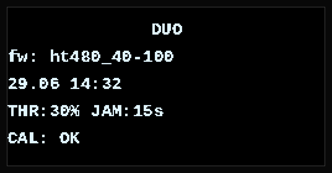
When powered on, the display also briefly shows the device information panel.
07Device placement
The receiving antennas (3.3 and 5.8 GHz) must be installed vertically, unobstructed by the enclosure, propellers, other antennas, or frame elements — this directly affects detection range.
08Startup procedure
Before starting the system, complete five steps in order:



For details on connecting antennas and VTX units, see “Pre-power-on check.”
09Pinout
Lower connector
| DC | 5.8 GHz VTX | 3.3 GHz VTX | 3.3 GHz VTX * | |||||||
| − | + | − | D | + | − | D | + | − | D | + |
| GND | VBAT | GND | DATA | VCC | GND | DATA | VCC | GND | DATA | VCC |
* second 3.3 GHz port — not used in the current version
Typical VTX pinout
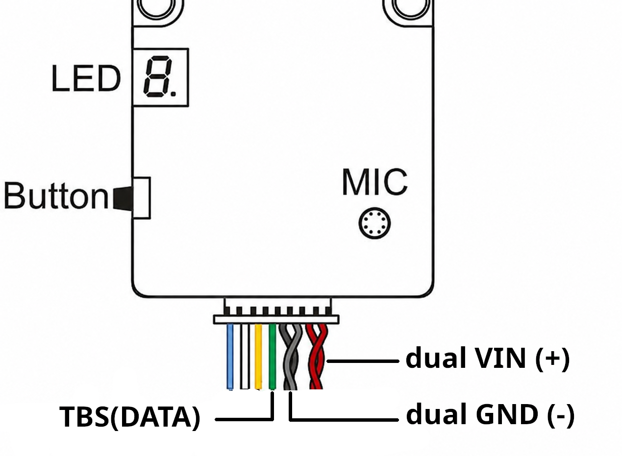
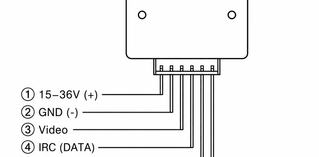
The pinout is provided for current VTX batches. Before connection, always check the markings on the board or the manufacturer's documentation — the pinout may change without notice.
10Calibration and settings
All control is performed with one button near the lower-right corner of the display.
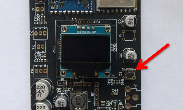
| Calibration | Hold the button while powering on. The device will automatically measure the noise level across all channels. The antennas must be connected. |
| Enter menu | During operation, hold the button. Release it when all four LEDs flash. The settings menu will open. |
| Select value | A short press cycles through the available parameter values. |
| Save | Hold the button until the LEDs flash, then release it. The value is saved. |
| Exit without changes | Do not press the button for 40 seconds. The device will resume operation with the previous settings. |
Current values are shown on the display. Settings are retained after power-off.
Calibration screen
First, a countdown before start (remove transmitters from the air), then measurement progress for both bands: the upper half of each bar is the baseline noise level; the lower half is the current pass.
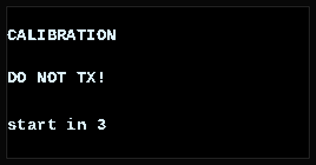
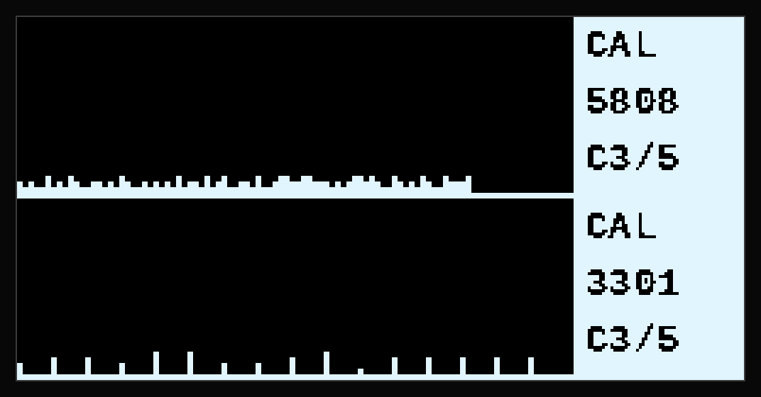
Menu screens
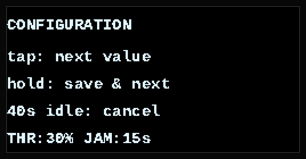
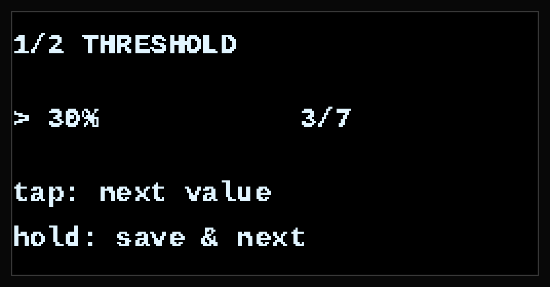
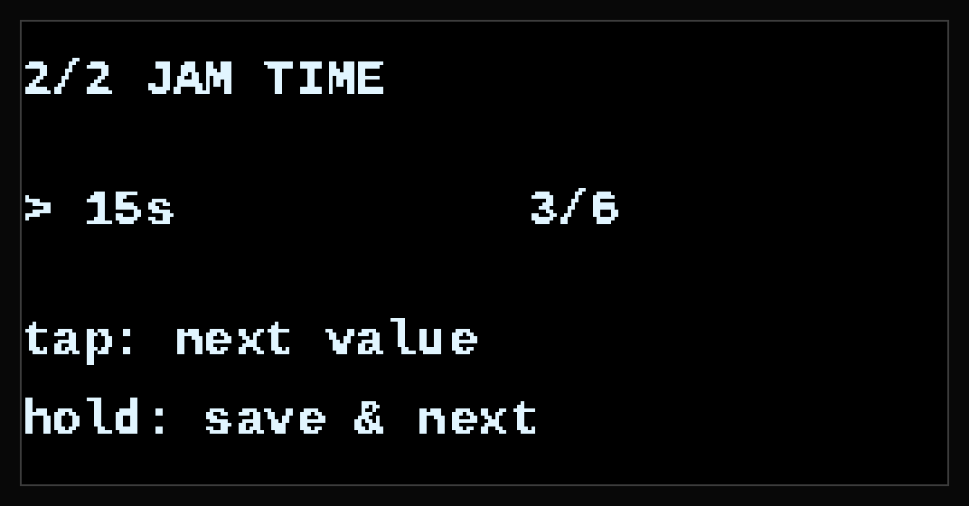
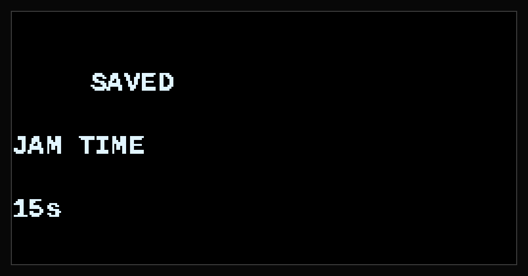
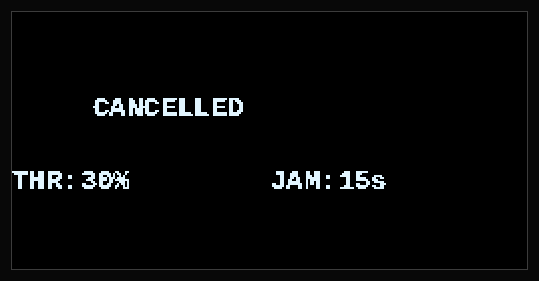
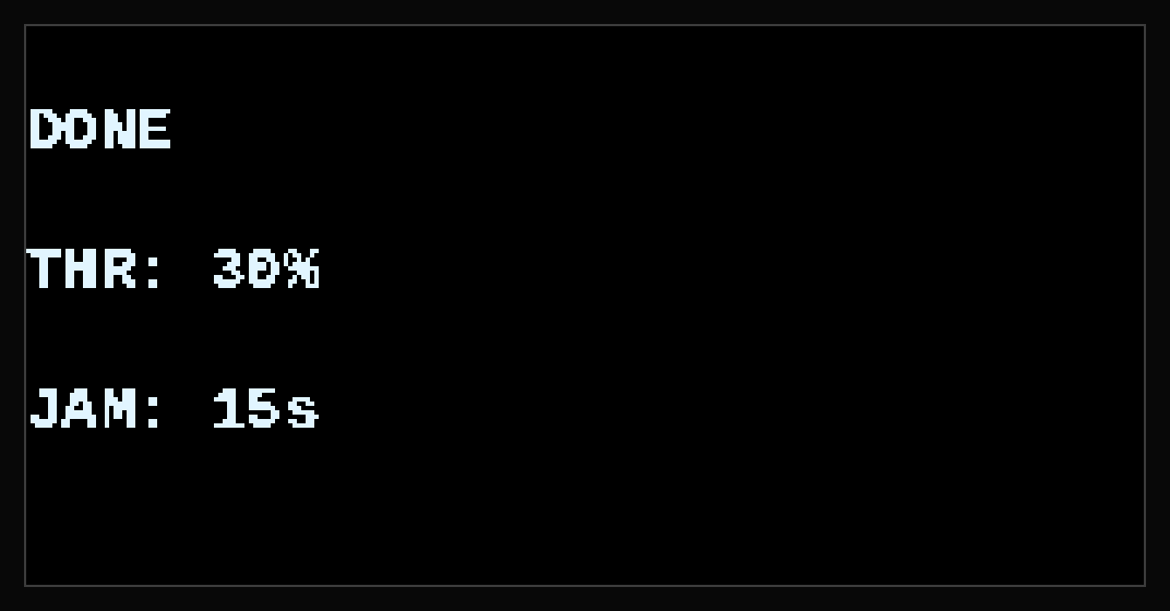
The screen illustrations were generated with the tools/oled_mockup tool from the actual firmware display logic — they are not screen photographs.
11Pre-power-on check
- □Antennas connected to all VTX units
- □SMA connectors tightened
- □Cables undamaged
- □VTX cooling provided
- □Power polarity correct
Workshop testing
- Use minimum VTX power.
- Provide forced cooling during the test.
- Keep the test drone at least 50 m away.
- Do not conduct prolonged tests without airflow.
If the test drone is too close, the strong signal may cause false triggers in the other band due to harmonics or overloading of internal components.

Combat use / field trials
- Install the system on the frame in the propeller airflow area.
- Make sure fans and heat sinks are not obstructed by mounting elements.
- Set VTX power to maximum (10W) using the button on the VTX enclosure. The VTX retains the power-level setting.
12Testing and expected behavior
Distance to the test drone
Symptom: the device “misses” the channel — it triggers on an adjacent channel instead of the one on which the drone is actually operating.
Cause: the test drone is too close (closer than 30–50 m). The strong signal overloads the receiver — the RSSI level is excessive on several adjacent channels at once, and the device cannot correctly determine the exact channel on which the drone is operating.
Correct procedure:
- test from a distance of 50 meters or more;
- with a clear line of sight between the drone and DUO;
- do not place the test drone directly above the device or right next to the antenna.
At this distance, the signal arrives at a normal level, DUO clearly identifies one channel, and activates targeted jamming on that channel. Under real conditions, an adversary FPV always operates at distances of hundreds of meters or more — this problem does not occur there.
VTX power setting
Cause: DUO does not control VTX power — it controls only the frequency (channel) on which the VTX generates interference. Power is set manually on the VTX itself, once; thereafter, the VTX always operates at that power.

General testing rules
- test in an open area without strong reflections (nearby metal hangars and concrete walls distort the results);
- do not operate a VTX without a connected antenna;
- during prolonged testing, monitor the VTX enclosure temperature by hand or with a thermometer;
- bench-test results do not always reproduce field conditions — distance, terrain, and the drone antenna type significantly affect operation.
13Troubleshooting
| Symptom | Possible cause | Remedy |
|---|---|---|
| Device does not respond to power-on | Power-supply problems | Check wire integrity and power-source parameters |
| No signal detection | Receiver-path antenna is disconnected or damaged | Check the antenna connection and SMA connector condition |
| Triggering on an adjacent channel | Test drone is too close (<50 m) — receiver overload | Increase the distance to the test signal |
| False detection on Band X (5.8 GHz) | Spurious emission from the test transmitter (e.g. AKK Alpha 10W) on these channels | Check whether the test VTX generates harmonics at the incorrectly detected frequencies |
| VTX does not activate at the detected frequency | VTX control cable is disconnected or damaged | Check the DATA/VCC/GND connections on the lower connector |
| VTX overheating | Placement/cooling recommendations were not followed | Make sure the VTX fan is unobstructed and the video transmitter itself is located in the propeller airflow area |
| Persistent false triggers | Calibration was not performed or was performed without connected antennas | Perform calibration with the antennas connected |
14Limitations
Effective against
- analog FPV video channels;
- continuous analog video signals;
- the range 3.3 GHz depending on the table variant — 3170–3470 MHz / 16 channels (A), 3060–3840 MHz / 80 channels (B) or 3000–4000 MHz / 101 channel (C);
- the range 4990–5945 MHz (5.8 GHz, 80 channels).
Not effective against
- digital video transmission systems (DJI, HDZero, Walksnail etc.);
- control and telemetry channels (868 / 915 MHz, 2.4 GHz);
- signals outside the device channel table.
Electromagnetic compatibility (EMC) and mutual interference
Powerful jammer transmitters may affect nearby equipment — satellite terminals (Starlink), digital video receivers, GPS, and telemetry. The level of impact depends on distance, power, antenna shielding, and the specific mounting configuration on the carrier, so general figures are of little use here.
Recommendation: before continuous operation in a specific configuration, check DUO compatibility with all equipment that will be located nearby on the same platform or position:
- turn on all adjacent equipment (satellite terminal, telemetry/control receivers, GPS) in normal operating mode;
- activate DUO jamming at maximum VTX power in both bands;
- check whether stable communication/lock of adjacent equipment is maintained throughout the entire jamming cycle;
- if failures occur, increase antenna separation and add shielding or filtering to the affected path.
Repeat the test after every significant layout change — a new antenna, a different platform, or new adjacent equipment.
15Overall enclosure dimensions
| Length | 160 mm |
| Width | 90 mm |
| Height | 25 mm |
| Mass (without antennas and VTX) | 150 g |
16Specifications
| Reception bands | 3.3 GHz — variant A: 3170–3470 MHz (16 ch.) · B: 3060–3840 MHz (80 ch.) · C: 3000–4000 MHz (101 ch.) 5.8 GHz: 4990–5945 MHz (80 ch.) |
| Full scan cycle | ~3.2 s (variant A) · ~5.5 s (B) · ~6.3 s (C) |
| Detection threshold (RSSI) | configured by the operator through the menu |
| Jamming duration | configured by the operator through the menu |
| Input voltage | 12–24 V DC |
| Consumption, scanning mode | up to 3.2 W |
| Maximum consumption (jamming in both bands) | up to 100 W |
| Display | OLED 128×64, I²C |
| Control | one button, on-display menu |
| Control-unit weight | 150 g |
| Complete-system weight | ~320 g |