SYCH-AIR Complex Operating Manual
Modifications: SYCH-AIR (1.2 GHz) / SYCH-AIR (3.3 GHz) / SYCH-AIR (5.8 GHz) / SYCH-AIR Diversity (5.8 + 3.3 GHz) / SYCH-AIR Trivercity (1.2 + 3.3 + 5.8 GHz)
DUO device
Device
- Top — two receive antenna inputs: 3.3 and 5.8 GHz
- Bottom — terminal block: DC power and control of the transmitters (VTX)
Our software products
Android and PC software: scanning and generating SDR radio signals on the HackRF board.


All projects — devices and software →
1. General description of the complex
The SYCH-AIR complex is designed to work with analog FPV video signals and is used as part of electronic countermeasures and FPV channel monitoring systems. The system provides reception, analysis, and processing of active analog video channels of FPV drones or other video signal sources operating in the corresponding frequency band.
The device operates in automatic mode and does not require complex settings from the operator. The design of the complex allows it to be integrated into various platforms and use different types of antennas depending on the application conditions.
The efficiency of the complex directly depends on the correct connection, the quality of the antenna path, the correct choice of the working channel, the presence of active cooling, and the placement conditions in space.


2. System Components
The complex includes:
- main SYCH control unit;
- control connection cable;
- VTX antenna;
- external video transmitter (VTX);
- power cables;
- auxiliary mounting and connection elements.
The components of the modification depend on the selected frequency band and the type of video transmitter. For each modification in the corresponding section below, there are separate images of the kit, connection diagrams, and photos of the respective video transmitters.
3. Objective Control Tools
3.1 FPV Video Scanner

The video signal scanner is used for objective control of the electronic warfare system's effectiveness by monitoring the radio ether in the working band of FPV video channels. During flight or before performing a task, the scanner allows the operator to observe the RSSI level (RSSI — received signal strength indicator: the higher the number, the stronger the signal the receiver sees), active channels, and changes in signal strength in real time.
In case of correct operation of the electronic warfare system, a decrease in the stability of the enemy's video signal, the appearance of noise, or a sharp drop in the reception level is recorded, which confirms the formation of an effective interference. Thus, the scanner acts as a feedback tool that allows evaluating whether the enemy's video channel is being blocked, and timely detecting areas of insufficient impact or changes in working frequencies.
4. Power Supply

The device is powered by a direct voltage source of 12–24 V (3S–6S Li-Po). It is recommended to use Li-Ion 4S–5S or a compatible Li-Po battery. The peak consumption of the system is up to 5 A. For stable operation, it is desirable to use a common grounding circuit (Ground).
4.1 Critical Warning
IT IS FORBIDDEN to turn on the video transmitter without a connected antenna!
Operating the VTX without an antenna can cause damage to the power amplifier in a matter of seconds.
Before each start, it is necessary to check the integrity of the pigtail (short antenna cable from the board to the connector — there should be no tears or sharp bends on it), the condition of the SMA connection (round threaded antenna connector — must be tightly screwed on), and the correct connection of the power cables.

5. Operating Mode and Indication
The electronic warfare device operates in the mode of continuous ether scanning. During scanning, the signal level (RSSI) on all channels is analyzed, and the channel with the highest signal level is determined.
LED indication:
- green indicator — no powerful signals, RSSI on all channels is at a low level;
- red indicator — a powerful signal is detected on one or more channels.
Display indication:
- top right — RSSI level of the strongest signal;
- bottom right — number of the channel with the maximum RSSI;
- histogram — shows the total number and distribution of signals by channels for visual assessment of the radio environment.
6. Device Placement
6.1 Placement in ground variant
For effective operation on the ground, it is necessary to ensure a clear zone around the antenna. The antenna must be installed vertically, without close obstacles within a radius of at least 15 cm. Covering the antenna with a housing, soil, leaves, or other obstacles reduces the system's effectiveness. An open area, a clear radio horizon, and a free Fresnel zone significantly improve the range.

6.2 Placement on UAV
When installing the device on a UAV, it is necessary to provide the maximum separation between the device's antenna and the GPS antenna (recommended at least 15–20 cm, preferably along different axes). This reduces mutual interference and prevents loss of GPS fix. The antenna must be installed vertically, without overlapping by frame elements, the battery, or power cables.
The VTX / SYCH AIR unit should be placed in the zone of active airflow from the propellers. It is forbidden to cover the radiator or install the module in places without ventilation. All cables must be securely fastened, without tension on the connectors.

7. Startup Algorithm
Before launching the complex, it is necessary to:
- check the fixation of connectors, integrity of cables and pigtails;
- ensure reliable connection of the SMA antenna to the VTX;
- check that the VTX radiator and fan are not blocked;
- connect the XT60, check the light indication and the absence of errors;
- wait for the system to fully boot (3–5 seconds).

8. Frequency architecture and VTX channels
The figure below shows the consolidated architecture of frequencies and channels of video transmitters for the three modifications of the complex. General information on setting the VTX power is also provided.

1.2 GHz — 9 channels (1373R)
| Band | CH1 | CH2 | CH3 | CH4 | CH5 | CH6 | CH7 | CH8 | CH9 |
|---|---|---|---|---|---|---|---|---|---|
| A | 1080 | 1120 | 1160 | 1200 | 1240 | 1258 | 1280 | 1320 | 1360 |
3.3 GHz — 16 channels (RushFPV) / 35 channels (Thor T35)
| Band | CH1 | CH2 | CH3 | CH4 | CH5 | CH6 | CH7 | CH8 |
|---|---|---|---|---|---|---|---|---|
| A | 3170 | 3190 | 3210 | 3230 | 3250 | 3270 | 3290 | 3310 |
| B | 3330 | 3350 | 3370 | 3390 | 3410 | 3430 | 3450 | 3470 |
5.8 GHz — 80 channels (AKK Alpha 10)
| Band | CH1 | CH2 | CH3 | CH4 | CH5 | CH6 | CH7 | CH8 |
|---|---|---|---|---|---|---|---|---|
| A | 5474 | 5492 | 5510 | 5528 | 5546 | 5564 | 5582 | 5600 |
| B | 5362 | 5399 | 5436 | 5473 | 5510 | 5547 | 5584 | 5621 |
| E | 5325 | 5348 | 5366 | 5384 | 5402 | 5420 | 5438 | 5456 |
| F | 5129 | 5159 | 5189 | 5219 | 5249 | 5279 | 5309 | 5339 |
| R | 4990 | 5020 | 5050 | 5080 | 5110 | 5140 | 5170 | 5200 |
| P | 5333 | 5373 | 5413 | 5453 | 5493 | 5533 | 5573 | 5613 |
| L | 4900 | 4940 | 4921 | 4958 | 4995 | 5032 | 5069 | 5099 |
| U | 5960 | 5980 | 6000 | 6020 | 6030 | 6040 | 6050 | 6060 |
| O | 5865 | 5845 | 5825 | 5805 | 5785 | 5765 | 5745 | 5725 |
| H | 5733 | 5752 | 5771 | 5790 | 5809 | 5828 | 5847 | 5866 |
9. SYCH-AIR Modification (1.2 GHz)
9.1 General Description
The SYCH-AIR (1.2) complex is designed to work with analog video signals in the 1.2–1.3 GHz band and is used as part of electronic countermeasures and FPV channel monitoring systems.
The system provides reception, analysis, and processing of active analog video channels of FPV drones or other video signal sources operating in the corresponding frequency band. The main element of the system is the video transmitter (VTX), which transmits the analog video signal from the camera or other signal source to the receiving equipment.
9.2 Components
The components of the modification include:
- main SYCH control unit;
- control connection cable;
- VTX antenna;
- external video transmitter RushFPV 1.2G VTX (4W).

9.3 Connection Diagram
9.4 Video Transmitter
The video transmitter used is RushFPV 1.2G VTX.
Role: transmission of analog video signal in the 1.2–1.3 GHz band.
Nominal output power: up to 4 W.

Power:
- the SYCH device does not control the VTX power — it is adjusted manually on the transmitter itself;
- before combat deployment, set the maximum power on the VTX;
- during testing, do not work at maximum power — this leads to rapid overheating;
- powerful VTXs must be placed on board the UAV with high-quality airflow.
Thermoregulation:
- mandatory presence of active cooling;
- forbidden to cover the transmitter housing;
- do not dismantle the cooling radiator.
9.5 VTX Channels Table (1.2 GHz)
Receiver 1373R — 9 channels, all values in MHz
| Band | CH1 | CH2 | CH3 | CH4 | CH5 | CH6 | CH7 | CH8 | CH9 |
|---|---|---|---|---|---|---|---|---|---|
| A | 1080 | 1120 | 1160 | 1200 | 1240 | 1258 | 1280 | 1320 | 1360 |
9.6 Alternative VTX — 1.2 GHz 10 W (more powerful)
To increase the transmission range, a more powerful analog video transmitter 1.2 GHz 10 W (9 channels, 1080–1360 MHz band) can be used. The channel grid is compatible with the 1373R receiver — the channel table matches the one given in paragraph 9.5.
- Power: up to 10 W (2.5 times more than the standard RushFPV 1.2G 4W);
- Band: 1080–1360 MHz, 9 channels;
- Cooling: mandatory active (radiator + propeller airflow);
- Source: AliExpress — Analog VTX FPV 1.2 GHz, 10 W, 9 channels.
Attention: at powers ≥10 W, it is strictly forbidden to turn on the transmitter without a connected antenna and without active airflow — this leads to failure in a matter of seconds.
10. SYCH-AIR Modification (3.3 GHz)
10.1 General Description
The SYCH-AIR (3.3) complex is designed to work with analog video signals in the 3.2–3.4 GHz band and is used as part of electronic countermeasures and FPV channel monitoring systems.
The system provides reception, analysis, and processing of active analog video channels of FPV drones or other video signal sources operating in the corresponding frequency band. The main element of the system is the video transmitter (VTX), which is used for transmission of analog video signal from the camera or other signal source.
10.2 Components
The components of the modification include:
- main SYCH control unit;
- control connection cable;
- VTX antenna;
- external video transmitter RushFPV 3.3G VTX (10W).

10.3 Connection Diagram
10.4 Video Transmitter
The video transmitter used is RushFPV 3.3G VTX.
Role: transmission of analog video signal in the 3.2–3.4 GHz band.
Nominal output power: up to 10 W.

Power:
- the SYCH device does not control the VTX power — it is adjusted manually on the transmitter itself;
- before combat deployment, set the maximum power on the VTX;
- during testing, do not work at maximum power — this leads to rapid overheating;
- powerful VTXs must be placed on board the UAV with high-quality airflow.
Thermoregulation:
- mandatory presence of active cooling;
- forbidden to cover the transmitter housing;
- do not dismantle the cooling radiator.
10.5 VTX Channels Table (3.3 GHz)
RushFPV 3.3G VTX — 16 channels (20 MHz step), all values in MHz
| Band | CH1 | CH2 | CH3 | CH4 | CH5 | CH6 | CH7 | CH8 |
|---|---|---|---|---|---|---|---|---|
| A | 3170 | 3190 | 3210 | 3230 | 3250 | 3270 | 3290 | 3310 |
| B | 3330 | 3350 | 3370 | 3390 | 3410 | 3430 | 3450 | 3470 |
10.6 Alternative VTX — Thor T35 (3W)
Reflashing allows using Thor T35 (power 3 W) with an extended range — 5 bands, 35 channels (3000–4040 MHz).
| Band | CH1 | CH2 | CH3 | CH4 | CH5 | CH6 | CH7 | CH8 |
|---|---|---|---|---|---|---|---|---|
| A | 3000 | 3030 | 3060 | 3090 | 3120 | 3150 | 3180 | 3210 |
| B | 3240 | 3270 | 3300 | 3330 | 3370 | 3400 | 3430 | 3470 |
| E | 3500 | 3530 | 3560 | 3590 | 3620 | 3650 | 3680 | 3710 |
| F | 3740 | 3770 | 3800 | 3830 | 3860 | 3890 | 3920 | 3950 |
| R | 3980 | 4010 | 4040 | — | — | — | — | — |
10.6.1 Extended mode — continuous sweep 3000–4000 MHz
In addition to the Thor T35 channel grid, a continuous 3.3 GHz sweep is supported — uniform scanning of the entire 3000–4000 MHz band with a step of 10 MHz (101 frequencies), without binding to the channel grid of a specific VTX. The mode is intended for searching atypical analog channels across the entire 3.0–4.0 GHz band.
| Band | +0 | +10 | +20 | +30 | +40 | +50 | +60 | +70 | +80 | +90 |
|---|---|---|---|---|---|---|---|---|---|---|
| 3000–3090 | 3000 | 3010 | 3020 | 3030 | 3040 | 3050 | 3060 | 3070 | 3080 | 3090 |
| 3100–3190 | 3100 | 3110 | 3120 | 3130 | 3140 | 3150 | 3160 | 3170 | 3180 | 3190 |
| 3200–3290 | 3200 | 3210 | 3220 | 3230 | 3240 | 3250 | 3260 | 3270 | 3280 | 3290 |
| 3300–3390 | 3300 | 3310 | 3320 | 3330 | 3340 | 3350 | 3360 | 3370 | 3380 | 3390 |
| 3400–3490 | 3400 | 3410 | 3420 | 3430 | 3440 | 3450 | 3460 | 3470 | 3480 | 3490 |
| 3500–3590 | 3500 | 3510 | 3520 | 3530 | 3540 | 3550 | 3560 | 3570 | 3580 | 3590 |
| 3600–3690 | 3600 | 3610 | 3620 | 3630 | 3640 | 3650 | 3660 | 3670 | 3680 | 3690 |
| 3700–3790 | 3700 | 3710 | 3720 | 3730 | 3740 | 3750 | 3760 | 3770 | 3780 | 3790 |
| 3800–3890 | 3800 | 3810 | 3820 | 3830 | 3840 | 3850 | 3860 | 3870 | 3880 | 3890 |
| 3900–3990 | 3900 | 3910 | 3920 | 3930 | 3940 | 3950 | 3960 | 3970 | 3980 | 3990 |
| 4000 | 4000 | — | ||||||||
101 frequencies with a uniform 10 MHz step cover the entire 3.0–4.0 GHz band without binding to the channel grid of a specific VTX.
10.7 Alternative VTX — 3.3 GHz 10 W, 16 channels (more powerful)
As a replacement for the standard RushFPV 3.3G VTX, an analogously characterized 10 W 3.3 GHz video transmitter with 16 channels can be used. The channel grid is compatible with RushFPV 3.3G — the channel table matches the one given in paragraph 10.5.
- Power: up to 10 W;
- Band: 3170–3470 MHz, 16 channels;
- Purpose: backup/alternative option in case RushFPV 3.3G is unavailable;
- Cooling: mandatory active (radiator + propeller airflow);
- Source: AliExpress — 10 W 3.3 GHz wireless VTX 16CH + VRX.
Attention: at powers ≥10 W, it is strictly forbidden to turn on the transmitter without a connected antenna and without active airflow — this leads to failure in a matter of seconds.
11. SYCH-AIR Modification (5.8 GHz)
11.1 General Description
The SYCH-AIR (5.8) complex is designed for the detection and analysis of active analog video channels of FPV drones, as well as for operation with external video transmitters (VTX) as part of electronic countermeasures systems.
Certain modifications allow recording video or analyzing the video signal for sync pulses to eliminate the possibility of false positives on a stable signal. In the standard configuration, the device only analyzes the signal, checking its stability, which reduces the possibility of triggering on digital systems.
11.2 Components
The components of the modification include:
- main SYCH control unit;
- control connection cable;
- VTX antenna;
- external video transmitter AKK Alpha 10 or AKK Alpha 25.

11.3 Connection Diagram
11.4 Video Transmitters


Video transmitters are used to transmit an analog video signal from a camera or other signal source in the operating band of the device. The nominal output power of the modules is up to 10 W.
Power:
- the SYCH device does not control the VTX power — it is adjusted manually on the transmitter itself;
- before combat deployment, set the maximum power on the VTX;
- during testing, do not work at maximum power — this leads to rapid overheating;
- powerful VTXs must be placed on board the UAV with high-quality airflow.
For stable operation, it is necessary to ensure:
- reliable antenna connection;
- active radiator cooling;
- absence of blocked ventilation openings.
11.5 VTX Channels Table (5.8 GHz)
AKK Alpha 10 — 80 channels (10 bands × 8 channels), all values in MHz
| Band | CH1 | CH2 | CH3 | CH4 | CH5 | CH6 | CH7 | CH8 |
|---|---|---|---|---|---|---|---|---|
| A | 5474 | 5492 | 5510 | 5528 | 5546 | 5564 | 5582 | 5600 |
| B | 5362 | 5399 | 5436 | 5473 | 5510 | 5547 | 5584 | 5621 |
| E | 5325 | 5348 | 5366 | 5384 | 5402 | 5420 | 5438 | 5456 |
| F | 5129 | 5159 | 5189 | 5219 | 5249 | 5279 | 5309 | 5339 |
| R | 4990 | 5020 | 5050 | 5080 | 5110 | 5140 | 5170 | 5200 |
| P | 5333 | 5373 | 5413 | 5453 | 5493 | 5533 | 5573 | 5613 |
| L | 4900 | 4940 | 4921 | 4958 | 4995 | 5032 | 5069 | 5099 |
| U | 5960 | 5980 | 6000 | 6020 | 6030 | 6040 | 6050 | 6060 |
| O | 5865 | 5845 | 5825 | 5805 | 5785 | 5765 | 5745 | 5725 |
| H | 5733 | 5752 | 5771 | 5790 | 5809 | 5828 | 5847 | 5866 |
Note. The models AKK Alpha 16W and AKK Alpha 25 support 96 channels (12 bands × 8 channels) — additionally bands T and N.
11b. SYCH-AIR Diversity Modification (5.8 + 3.3 GHz, dual band)
11b.1 General Description
The SYCH-AIR Diversity complex is a combined dual-band modification that simultaneously scans 5.8 GHz and 3.3 GHz and automatically activates the corresponding video transmitters based on the found signal. Inside the unit, two receivers (RX5808 + RX3301) with a common SPI bus and three VTX control outputs are installed: one for 5.8 GHz and two for 3.3 GHz (wide Tramp + T35 SmartAudio).
The device operates in automatic mode. No manual switching between bands is required — the system itself determines the band by the frequency of the detected signal and activates the correct VTX. This modification is useful where the FPV target can be on either of the two bands, or on the field where 3.3 GHz and 5.8 GHz devices are present simultaneously.
11b.2 Components
The components of the modification include:
- main SYCH Diversity control unit;
- control connection cable;
- 5.8 GHz VTX antenna;
- 3.3 GHz VTX antenna (one, feeds both 3.3 transmitters through a splitter);
- 5.8 GHz video transmitter — AKK Alpha 10 or AKK Alpha 25;
- 3.3 GHz video transmitter (Tramp, narrow) — RushFPV 3.3G VTX (10 W);
- 3.3 GHz video transmitter (SmartAudio, extended) — Thor T35 (3 W) (support will appear in one of the next firmwares).
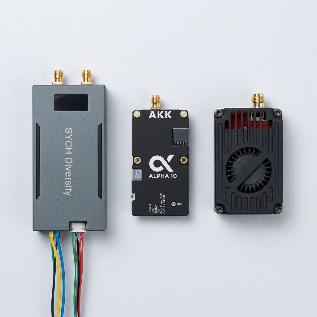
11b.3 Connection Diagram
11b.4 Video Transmitters
The modification includes three video transmitters, one for each output of the control unit:
- 5.8 GHz — AKK Alpha 10 / 25, SmartAudio, up to 10 W nominal output power. 80 channels (A10) / 96 channels (A25).
- 3.3 GHz (narrow) — RushFPV 3.3G VTX, Tramp, 10 W, 16 channels in the 3170–3470 MHz band.
- 3.3 GHz (extended) — Thor T35, SmartAudio, 3 W, 5 bands 3000–4040 MHz (designed to operate outside the narrow RushFPV window). T35 support in the Diversity modification will be added in one of the next firmwares — the hardware VTX is already installed and connected.
Control is automatic. In the 5.8 GHz band, the interference is created by AKK. In the 3.3 GHz band in the current firmware, the interference is created by RushFPV 3.3G in the 3170–3470 MHz window. After a firmware update, Thor T35 will be activated, and the combined logic will apply: in the 3170–3470 MHz window, RushFPV and T35 work simultaneously (dual coverage), and outside this window (below 3170 or above 3470 MHz), only T35 works. For targets simultaneously on 5.8 and 3.3, all active VTXs are turned on in parallel.
Power — for all three VTXs:
- the SYCH device does not control the VTX power — it is adjusted manually on each transmitter separately;
- before combat deployment, set the maximum power on all three VTXs;
- during testing, do not work at maximum power — this leads to rapid overheating;
- powerful VTXs must be placed on board the UAV with high-quality airflow.
Thermoregulation — for all three VTXs:
- mandatory active cooling;
- forbidden to block ventilation openings;
- do not dismantle the cooling radiator.
11b.5 Operation Algorithm
The scanning cycle proceeds in turn: first 80 channels of 5.8 GHz (via RX5808), then 33 channels of 3.3 GHz (via RX3301). If the signal level exceeds the threshold, the corresponding VTX is activated at the detection frequency, jamming is performed for 30 seconds, after which the cycle repeats.
Detection thresholds (RSSI, %) are set separately for each band because the baseline RSSI levels on the two receivers differ. Standard values: 5.8 GHz — 15%, 3.3 GHz — 35%.
11b.6 VTX Channels Table
5.8 GHz — AKK Alpha 10 (80 channels, 10 bands × 8 channels, values in MHz):
| Band | CH1 | CH2 | CH3 | CH4 | CH5 | CH6 | CH7 | CH8 |
|---|---|---|---|---|---|---|---|---|
| A | 5474 | 5492 | 5510 | 5528 | 5546 | 5564 | 5582 | 5600 |
| B | 5362 | 5399 | 5436 | 5473 | 5510 | 5547 | 5584 | 5621 |
| E | 5325 | 5348 | 5366 | 5384 | 5402 | 5420 | 5438 | 5456 |
| F | 5129 | 5159 | 5189 | 5219 | 5249 | 5279 | 5309 | 5339 |
| R | 4990 | 5020 | 5050 | 5080 | 5110 | 5140 | 5170 | 5200 |
| P | 5333 | 5373 | 5413 | 5453 | 5493 | 5533 | 5573 | 5613 |
| L | 4900 | 4940 | 4921 | 4958 | 4995 | 5032 | 5069 | 5099 |
| U | 5960 | 5980 | 6000 | 6020 | 6030 | 6040 | 6050 | 6060 |
| O | 5865 | 5845 | 5825 | 5805 | 5785 | 5765 | 5745 | 5725 |
| H | 5733 | 5752 | 5771 | 5790 | 5809 | 5828 | 5847 | 5866 |
Note. The models AKK Alpha 16W and AKK Alpha 25 support 96 channels (12 bands × 8) — additionally bands T and N.
3.3 GHz — RushFPV 3.3G VTX (16 channels, 20 MHz step, values in MHz):
| Band | CH1 | CH2 | CH3 | CH4 | CH5 | CH6 | CH7 | CH8 |
|---|---|---|---|---|---|---|---|---|
| A | 3170 | 3190 | 3210 | 3230 | 3250 | 3270 | 3290 | 3310 |
| B | 3330 | 3350 | 3370 | 3390 | 3410 | 3430 | 3450 | 3470 |
3.3 GHz — Thor T35 (35 channels, 5 bands, 3000–4040 MHz):
| Band | CH1 | CH2 | CH3 | CH4 | CH5 | CH6 | CH7 | CH8 |
|---|---|---|---|---|---|---|---|---|
| A | 3000 | 3030 | 3060 | 3090 | 3120 | 3150 | 3180 | 3210 |
| B | 3240 | 3270 | 3300 | 3330 | 3370 | 3400 | 3430 | 3470 |
| E | 3500 | 3530 | 3560 | 3590 | 3620 | 3650 | 3680 | 3710 |
| F | 3740 | 3770 | 3800 | 3830 | 3860 | 3890 | 3920 | 3950 |
| R | 3980 | 4010 | 4040 | — | — | — | — | — |
11b.7 Extended mode — continuous sweep 3000–4000 MHz
In addition to the Thor T35 channel grid, the 3.3 GHz band supports a continuous sweep — uniform scanning of the entire 3000–4000 MHz band with a step of 10 MHz (101 frequencies), without binding to the channel grid of a specific VTX. The mode is intended for searching atypical analog channels across the entire 3.0–4.0 GHz band.
| Band | +0 | +10 | +20 | +30 | +40 | +50 | +60 | +70 | +80 | +90 |
|---|---|---|---|---|---|---|---|---|---|---|
| 3000–3090 | 3000 | 3010 | 3020 | 3030 | 3040 | 3050 | 3060 | 3070 | 3080 | 3090 |
| 3100–3190 | 3100 | 3110 | 3120 | 3130 | 3140 | 3150 | 3160 | 3170 | 3180 | 3190 |
| 3200–3290 | 3200 | 3210 | 3220 | 3230 | 3240 | 3250 | 3260 | 3270 | 3280 | 3290 |
| 3300–3390 | 3300 | 3310 | 3320 | 3330 | 3340 | 3350 | 3360 | 3370 | 3380 | 3390 |
| 3400–3490 | 3400 | 3410 | 3420 | 3430 | 3440 | 3450 | 3460 | 3470 | 3480 | 3490 |
| 3500–3590 | 3500 | 3510 | 3520 | 3530 | 3540 | 3550 | 3560 | 3570 | 3580 | 3590 |
| 3600–3690 | 3600 | 3610 | 3620 | 3630 | 3640 | 3650 | 3660 | 3670 | 3680 | 3690 |
| 3700–3790 | 3700 | 3710 | 3720 | 3730 | 3740 | 3750 | 3760 | 3770 | 3780 | 3790 |
| 3800–3890 | 3800 | 3810 | 3820 | 3830 | 3840 | 3850 | 3860 | 3870 | 3880 | 3890 |
| 3900–3990 | 3900 | 3910 | 3920 | 3930 | 3940 | 3950 | 3960 | 3970 | 3980 | 3990 |
| 4000 | 4000 | — | ||||||||
101 frequencies with a uniform 10 MHz step cover the entire 3.0–4.0 GHz band without binding to the channel grid of a specific VTX.
11c. SYCH-AIR Trivercity Modification (1.2 + 3.3 + 5.8 GHz, tri-band)
11c.1 General Description
SYCH-AIR Trivercity is a tri-band autonomous device for the simultaneous detection and suppression of analog FPV video signals from UAVs in three bands: 1.2 GHz, 3.3 GHz, and 5.8 GHz. Three independent receivers and three video transmitter control outputs are installed on a single board, one for each band. The scanner monitors the ether in the background; after confirming the signal, the device launches targeted suppression at the detected frequency.
Implementation: AVR ATmega328 · 16 MHz, 128×64 OLED display with three horizontal zones (one per band), EEPROM configuration (RSSI thresholds, suppression time, whitelist of frequencies — up to 3 per band). Board dimensions — 100 × 90 mm, 4 mounting holes in the corners.
11c.2 Control Board
11c.3 Bands and Channels
Three completely independent channels of reception and control, connected by a common SPI bus:
- 5.8 GHz — RX5808 receiver, 80 channels (10 bands × 8), 4990–5945 MHz band. VTX: AKK Alpha 10 / 25, SmartAudio protocol, up to 10 W.
- 3.3 GHz — RX3301 receiver, 16 channels, 3170–3470 MHz band. VTX: RushFPV 3.3G VTX, Tramp protocol, 10 W.
- 1.2 GHz — SK1200 / FT1200 PLL receiver, 8 channels (with expansion to 18, 1000–2300 MHz band). VTX: RushFPV 1.2G VTX, Tramp protocol, up to 4 W.
Alternative execution: the 1.2 GHz module can be replaced with an RX7500 (6.2–7.5 GHz, 64 channels) — for working with atypical analog channels in the upper part of the C-band.
11c.3.1 Extended 3.3 GHz mode — continuous sweep 3000–4000 MHz
In addition to the standard RushFPV channel grid (16 channels, 3170–3470 MHz), the 3.3 GHz channel supports a continuous sweep — uniform scanning of the entire 3000–4000 MHz band with a step of 10 MHz (101 frequencies), without binding to the channel grid of a specific VTX. The mode is intended for searching atypical analog channels across the entire 3.0–4.0 GHz band.
| Band | +0 | +10 | +20 | +30 | +40 | +50 | +60 | +70 | +80 | +90 |
|---|---|---|---|---|---|---|---|---|---|---|
| 3000–3090 | 3000 | 3010 | 3020 | 3030 | 3040 | 3050 | 3060 | 3070 | 3080 | 3090 |
| 3100–3190 | 3100 | 3110 | 3120 | 3130 | 3140 | 3150 | 3160 | 3170 | 3180 | 3190 |
| 3200–3290 | 3200 | 3210 | 3220 | 3230 | 3240 | 3250 | 3260 | 3270 | 3280 | 3290 |
| 3300–3390 | 3300 | 3310 | 3320 | 3330 | 3340 | 3350 | 3360 | 3370 | 3380 | 3390 |
| 3400–3490 | 3400 | 3410 | 3420 | 3430 | 3440 | 3450 | 3460 | 3470 | 3480 | 3490 |
| 3500–3590 | 3500 | 3510 | 3520 | 3530 | 3540 | 3550 | 3560 | 3570 | 3580 | 3590 |
| 3600–3690 | 3600 | 3610 | 3620 | 3630 | 3640 | 3650 | 3660 | 3670 | 3680 | 3690 |
| 3700–3790 | 3700 | 3710 | 3720 | 3730 | 3740 | 3750 | 3760 | 3770 | 3780 | 3790 |
| 3800–3890 | 3800 | 3810 | 3820 | 3830 | 3840 | 3850 | 3860 | 3870 | 3880 | 3890 |
| 3900–3990 | 3900 | 3910 | 3920 | 3930 | 3940 | 3950 | 3960 | 3970 | 3980 | 3990 |
| 4000 | 4000 | — | ||||||||
101 frequencies with a uniform 10 MHz step cover the entire 3.0–4.0 GHz band without binding to the channel grid of a specific VTX.
11c.4 Interface and Control
- Display: 128×64 OLED with three horizontal zones — one for each band, showing current frequency and RSSI level.
- Configuration: 25-byte EEPROM — RSSI threshold values (separately for each band), suppression time, whitelist of frequencies.
- Whitelist of frequencies: up to 3 frequencies per band (whitelist for friendly drones — the device does not react to these frequencies).
- Suppression timer: default value 30 s (changed via CFG).
- Algorithm: cyclic scanning in turn 1.2 → 3.3 → 5.8 GHz; when the RSSI threshold is exceeded — activation of the corresponding VTX at the detection frequency. For simultaneous targets on several bands, the corresponding VTXs are activated in parallel.
12. Limitations and Features of Operation
12.1 Effective against
- analog FPV video channels;
- continuous analog video signal;
- 1080–1360 MHz band;
- 3200–3380 MHz band;
- 4990–5965 MHz band.
12.2 Not effective against
- digital video transmission systems (DJI, Autel, etc.);
- control and telemetry channels 868 / 915 MHz.
12.3 EMC and Mutual Interference
High-power video transmitters (approximately 16 W and higher) can cause significant interference to the operation of Starlink terminals and other equipment operating in close frequency bands.
The level of impact depends on the distance, type of antennas, shielding, filtering, and system configuration.
During preliminary tests, it was noticed that a receiver installed on the Bomber platform and designed to operate with a digital video signal in the 5.8 GHz band can react to powerful signals from third-party digital video transmitters. Even transmitters with a power of about 4 W can create such a strong signal near the receiving path that it leads to overloading or false triggering of the receiver.
Planned measures: additional tests using RF filtering are currently planned, specifically filters that cut off the lower part of the 5 GHz band, which is partially occupied by digital video transmission systems. The purpose of the testing is to evaluate the effectiveness of reducing spurious signals and increasing the selectivity of the receiving path.
13. Methodology of Proper Testing
This section explains how to correctly test the operation of the SYCH-AIR complex in field conditions. Following the methodology allows distinguishing the normal behavior of the device from false positives and avoiding VTX failure due to overheating.
13.1 Distance to the test drone
Symptom: the device 'misses' the channel — it triggers on adjacent channels (for example, E3, P1, A5) instead of the one on which the drone actually operates.
Cause: the test drone is located too close (closer than 30–50 m) to SYCH-AIR. A powerful signal 'blinds' the receiver — the RSSI level peaks simultaneously on several adjacent channels, and the device cannot correctly determine exactly which channel the drone is operating on.
How to do it correctly:
- test from a distance of 50 meters and further;
- in line-of-sight conditions between the drone and SYCH-AIR;
- do not position the test drone directly above the device or close to the antenna.
At this distance, the signal arrives at a normal level, SYCH-AIR clearly isolates one channel and spot-turns on the suppression exactly on it. In real combat conditions, an enemy FPV always operates at distances of hundreds of meters and further — this problem does not arise there.
13.2 VTX Power Setting
Symptom: it seems that the device works 'weakly' — VTX outputs a power level of 1 instead of 5.
Cause: SYCH-AIR does not control the VTX power — it only controls the frequency (channel) on which the VTX forms the interference. Power is set manually directly on the VTX itself.
How to do it correctly:
- before installation on a drone or in position, set the VTX power to maximum — level 5 (or «L» on the AKK Alpha display);
- for most VTXs this is done manually once — then it works at this power, SYCH-AIR only switches channels. The exception is compatible AKK Alpha 16W/25, which the firmware can switch power itself (section 16);
- for RushFPV 1.2G / 3.3G, power is set with a button on the VTX itself (more details in the video transmitter manufacturer's documentation).
⚠ Heat dissipation at maximum power — 10–30 W.
DO NOT test on the table without airflow at maximum power — VTX will overheat and fail in a matter of minutes.
How to cool down during testing:
- on a drone, cooling is provided by the airflow from the propellers;
- on the ground — raise on a mast or provide airflow with a powerful fan;
- during stationary testing on a table — reduce VTX power to level 1–2 and turn on briefly.
13.3 General testing rules
- test in an open area without strong reflections (metal hangars, concrete walls nearby distort the picture);
- do not start VTX without a connected antenna — see section 4. Power Supply, critical warning;
- during prolonged testing, control the temperature of the VTX housing by hand or with a thermometer;
- bench testing results do not always replicate the field picture — distance, landscape, and drone antenna type significantly affect operation.
14. Troubleshooting
| Symptom | Possible cause | Troubleshooting method |
|---|---|---|
| Missing video signal | Camera not connected or missing VIDEO signal | Check video camera connection and VIDEO cable |
| No signal | VTX antenna not connected or damaged | Check antenna connection and condition of SMA connector |
| Overheating of the video transmitter | Insufficient cooling or blocked radiator | Provide active airflow and free air access to the radiator |
| Unstable or weak signal | Incorrectly selected channel or existing interference | Check channel frequency and VTX settings |
15. Enclosure Overall Dimensions
| Parameter | Value |
|---|---|
| Length | 120 mm |
| Width | 50 mm |
| Height | 20 mm |
| Weight (without battery and VTX) | up to 120 g |

16. Additional Features and Settings
The power of the video transmitters (VTX) is set before starting the system in accordance with the technical requirements and conditions of application.
For AKK Alpha 16W and AKK Alpha 25 models, the ability to switch the power level by firmware means is provided.
For other models, software power switching via the device interface is not provided.
Using the firmware, the user can change:
- channel scanning period;
- duration and logic of signal suppression.
16.1 Access to firmware
The current firmware version, flashing instructions, and setup parameters are available via QR code:

17. Interaction with Friendly Drones (Tunnel)
The device operates on the principle of frequency suppression and does not distinguish 'friend / foe' signals, so the 'tunnel' mode is used for simultaneous operation with friendly UAVs.
In this mode, most of the band is covered by interference, and a 'window for ours' (Safe Zone) is formed in a predefined range, where friendly drones can stably transmit video without the impact of suppression.